
Setting the Stage of Uncertainty
Consider a nine-story high-rise multi-unit residential property constructed circa 1990 with a failing concrete brick façade. Due to areas of brick cracking and walls out of plumb, the owner had originally engaged a contractor to perform retrofit helical brick tie installation. For a variety of reasons, including escalating costs, the work was halted with only about 25% of the work complete.
Among our challenges would be confirming the extent and sufficiency of repair work already completed, and developing and implementing an effective retrofit solution for the façade. These challenges needed to be addressed in an environment of relative uncertainty, as is the case with existing buildings. The focus of this article will be on the design and implementation of repairs, including those related to concealed conditions.
Challenge 1: Lateral Support – Brick Ties
Several original construction deficiencies related to the lateral support systems were uncovered during our initial investigation, including improperly installed and failed brick ties at steel stud back-up walls and inconsistent brick tie spacing at cast-in-place concrete back-up.
Wall areas with steel stud back-up were designed with wire and plate style ties (also referred to as unit ties). These ties consist of a steel plate connected to the steel stud back-up, with a slotted connection protruding through the exterior sheathing to accommodate the wire tie, which is embedded in mortar (Figure 1). The existing tie spacing was 16-in. horizontally by 24-in. vertically. The horizontal spacing is consistent with interior metal stud spacing.
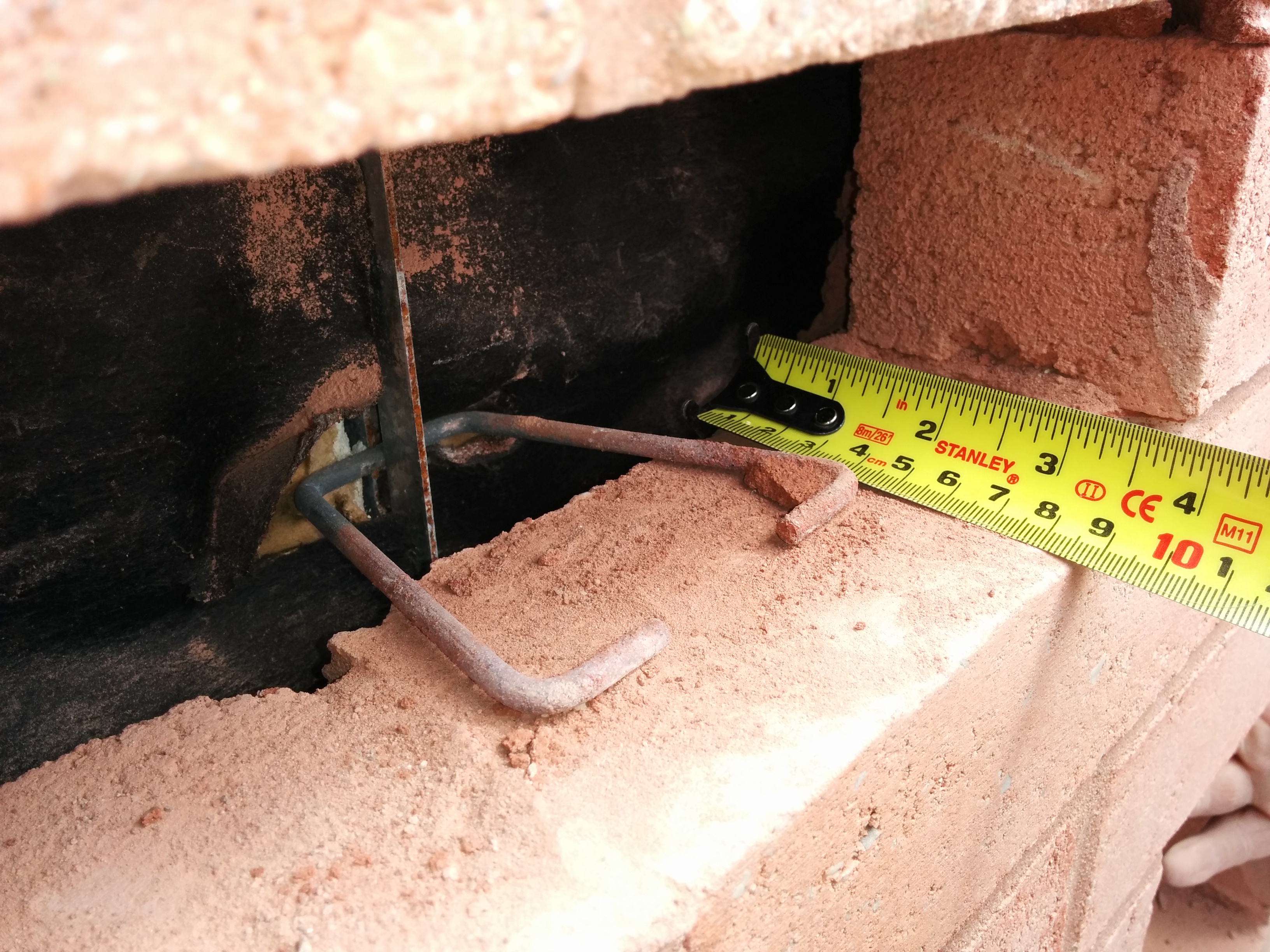
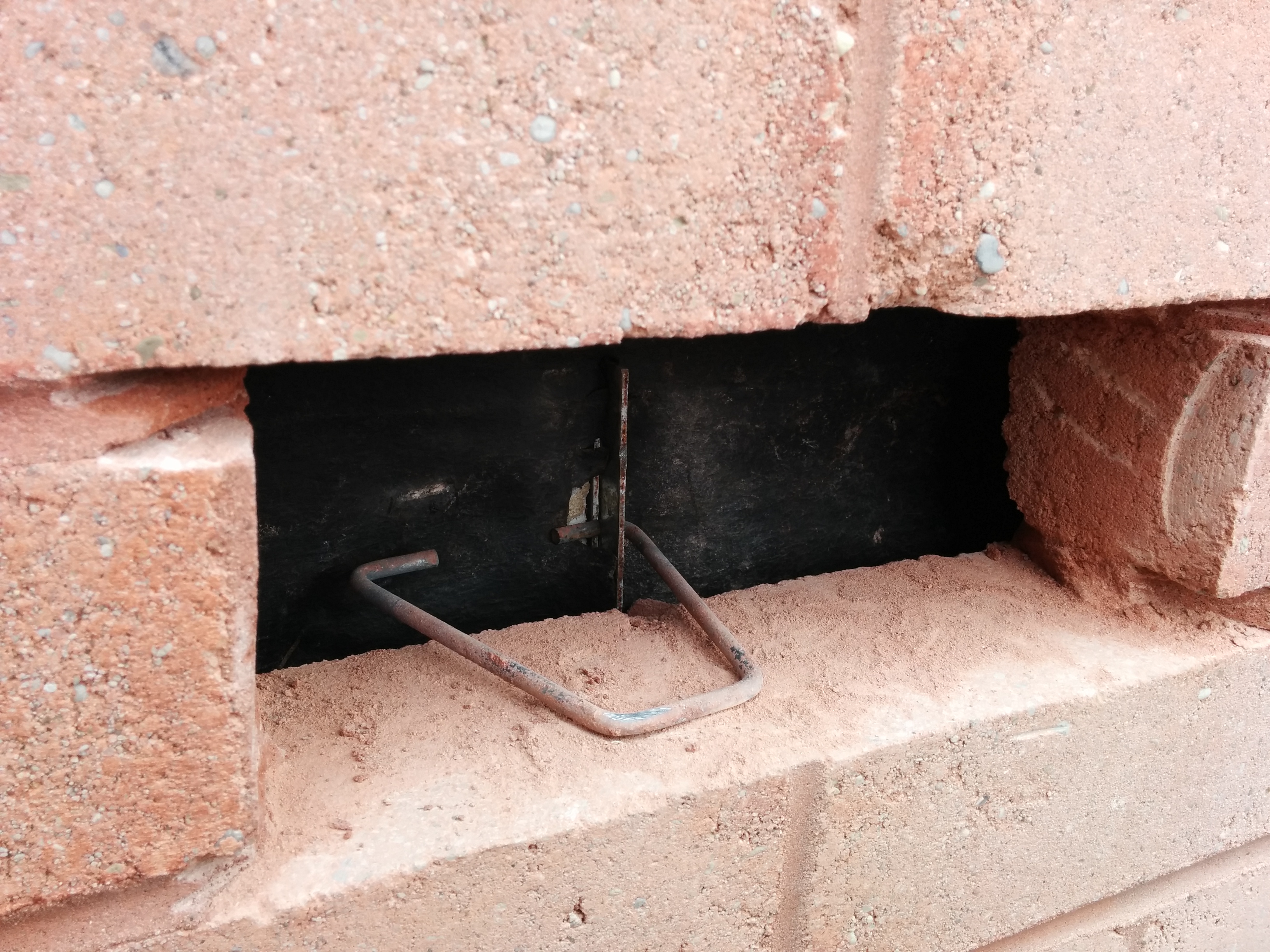
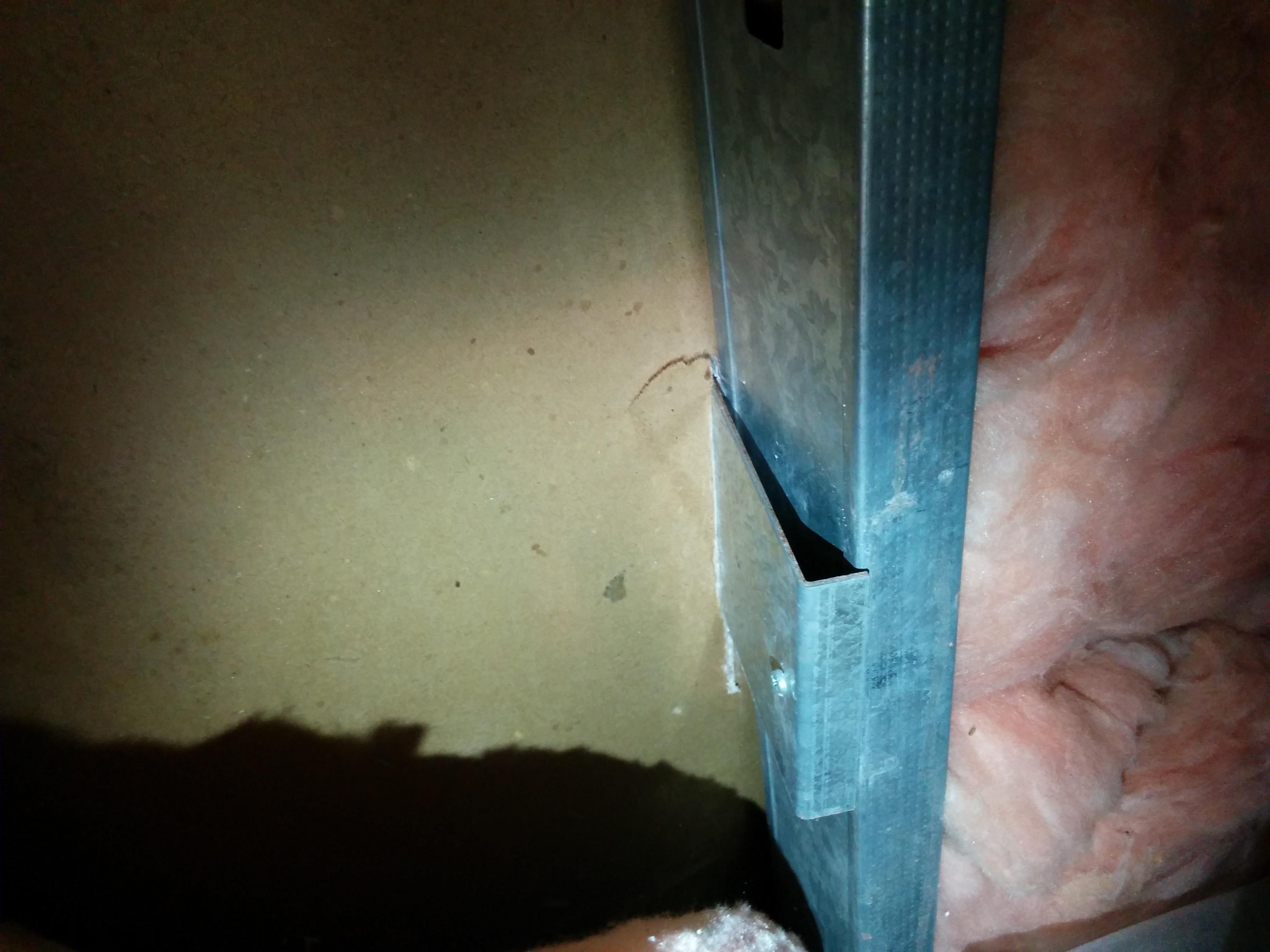
At over 50% of locations reviewed, wire ties were installed backwards, relying only on the back-turned leg of the tie to provide lateral support (Figure 2). Further, we uncovered disconnected plate connections at steel stud back-up (Figure 3) at 12% of interior test openings performed.
At areas with cast-in-place concrete back-up, dovetail-style brick ties were installed (Figure 4), but similar to the wire and plate ties, there were issues with the original installation. The dovetail tie spacing was inconsistent in both the horizontal and vertical directions. The dovetail ties are installed in vertical metal tracks that are cast into the wall structure. During our review, we discovered track spacing varying from 19-in. to 26-in. horizontally, and vertical tie spacing varying from 12-in. to over 50-in.
Based on loading calculations, it was determined that the inconsistent tie installation dictated that the existing system could not be reasonably relied upon.
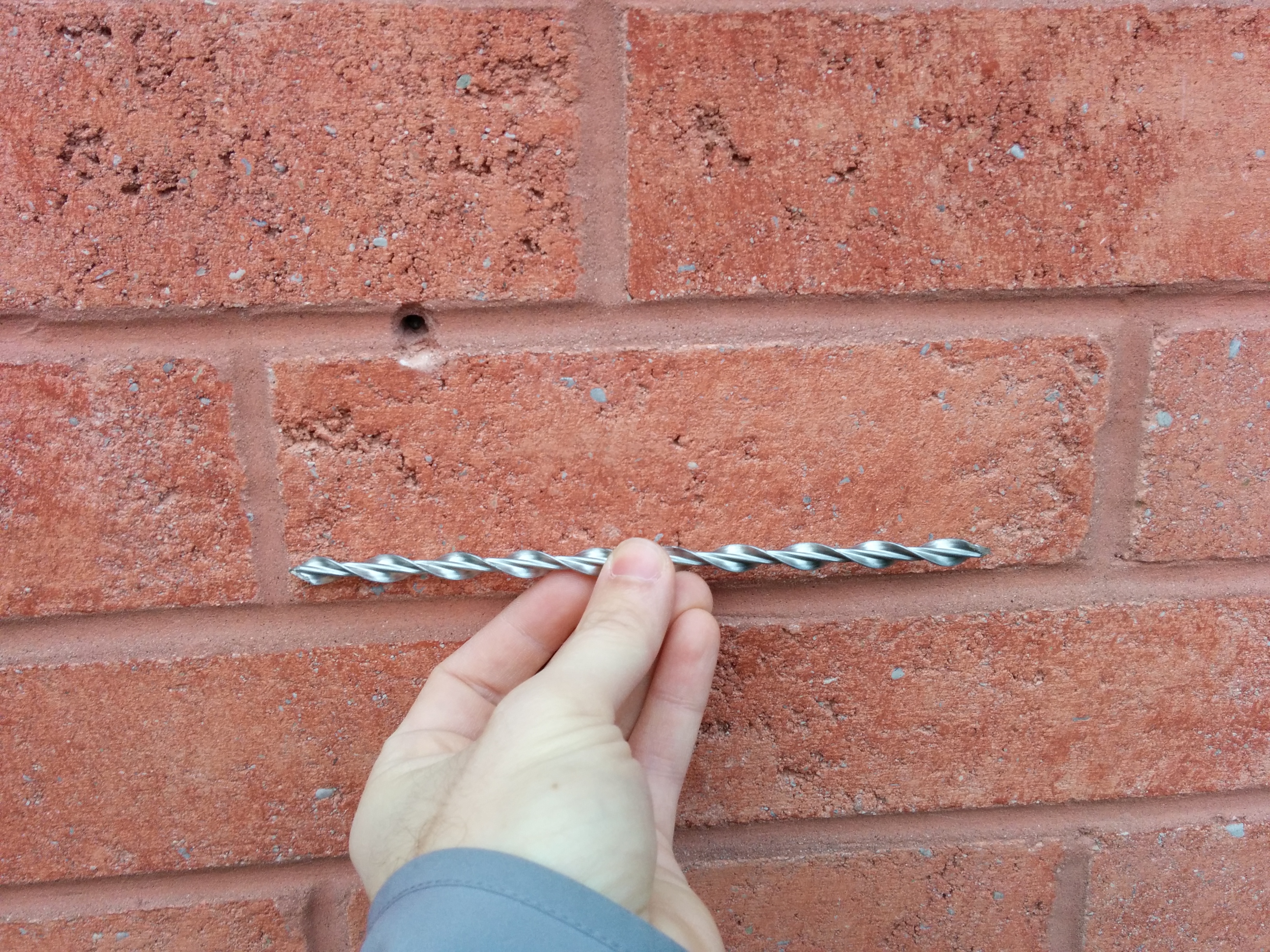
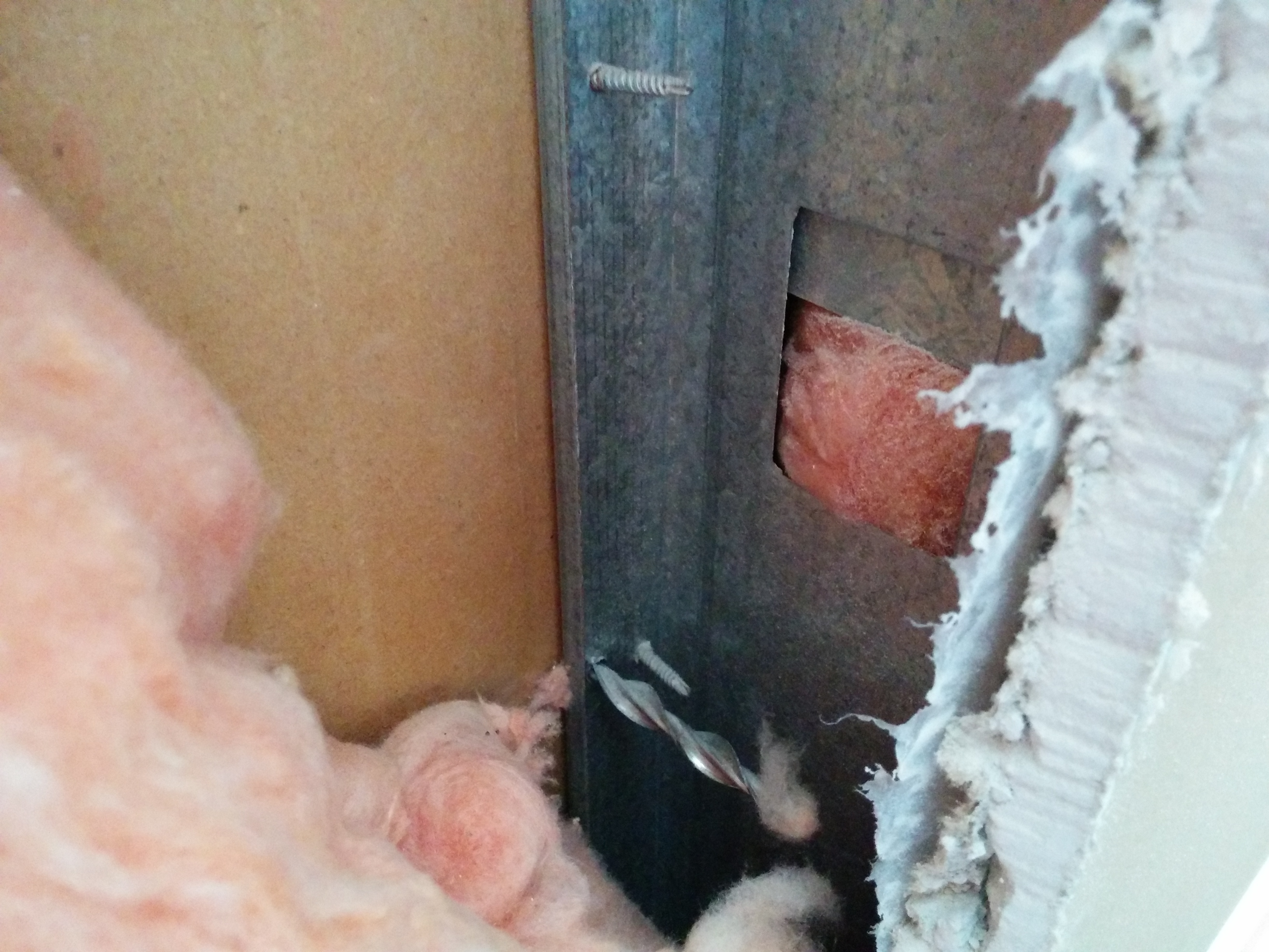
Lateral support would be re-established with new stainless steel retrofit helical brick ties at both steel stud back-up and concrete back-up. These ties are installed by first pre-drilling a pilot hole through the mortar joint and back-up (Figure 5), then drilling the helical tie through the mortar joint and into the back-up structure (Figure 6). A small mortar joint repair to conceal the tie completes the installation. Suitability of this application was established through pull-out testing throughout the installation process to ensure adequate lateral support at the façade.
Previous repairs were performed using a brick tie design requiring ten retrofit ties per stud (or per 16-in. spacing) per floor. The design and installation were applied to all wall areas. However, understanding that wind loading varies throughout the façade, we applied higher wind loading at some building areas such as corners and upper floor corners, and lower loading requirements at remaining wall areas. Accounting for flexible and rigid back-up wall systems, we were able to tune the retrofit tie design to require ten ties per stud at upper floor corners, nine ties per stud at remaining floor corners, and only eight ties per stud at remaining areas. This material reduction resulted in a significant cost savings for the owner.
Challenge 2: Brick Support at Shelf Angles
In addition to the lateral support concerns, our review uncovered issues related to excessive brick overhang at shelf angles. Steel shelf angles are installed at building floor slab edges. Each angle supports one story of the brick façade, and there should be engineered joints—a gap between the angle and brick sealed with a flexible sealant—at the top of each brick panel to accommodate movement. In many areas, bricks had been installed beyond the toe of the shelf angle so far that the engineered joint was instead filled with mortar, to provide support to the brick above. Of course, this use of mortar also facilitated load transfer to the shelf angles below, resulting in possible overloading concerns. It’s important to note that the brick installation was an original construction defect, and that we did not observe major signs of structural distress that would indicate immediate safety concerns or risk of sudden movement.
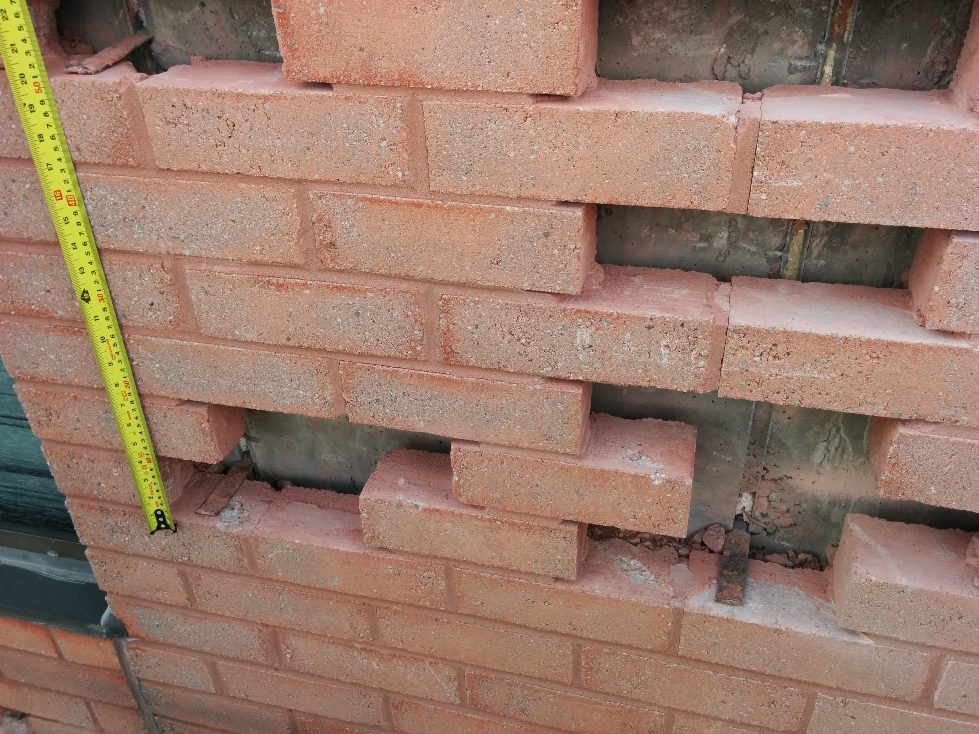
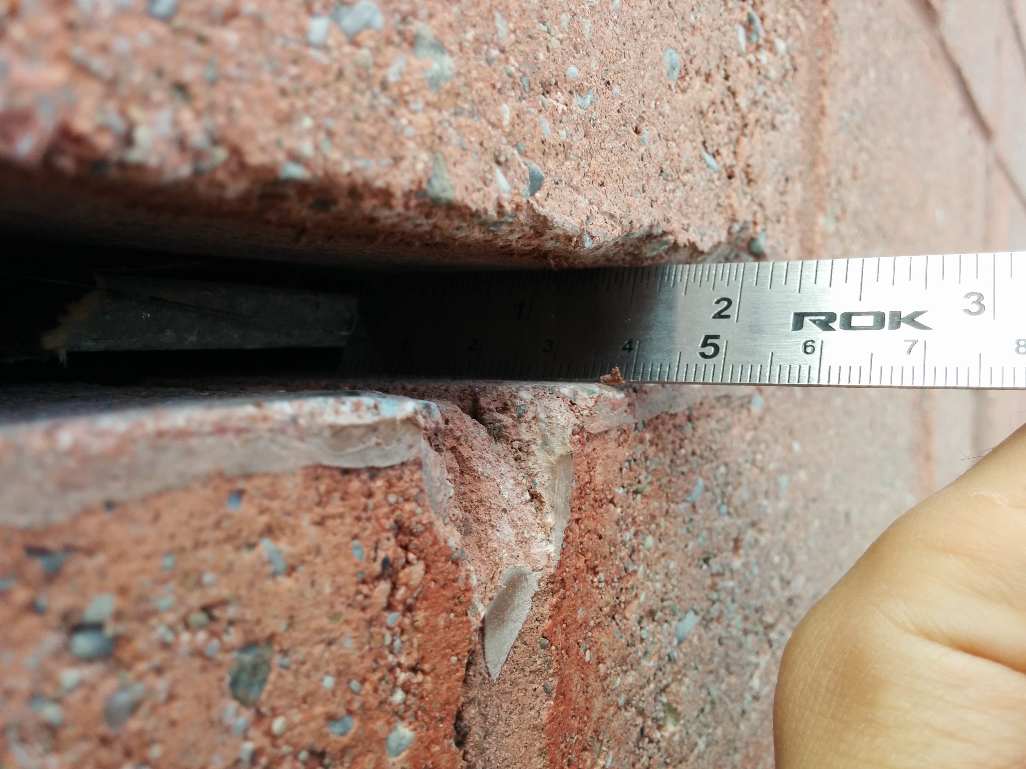
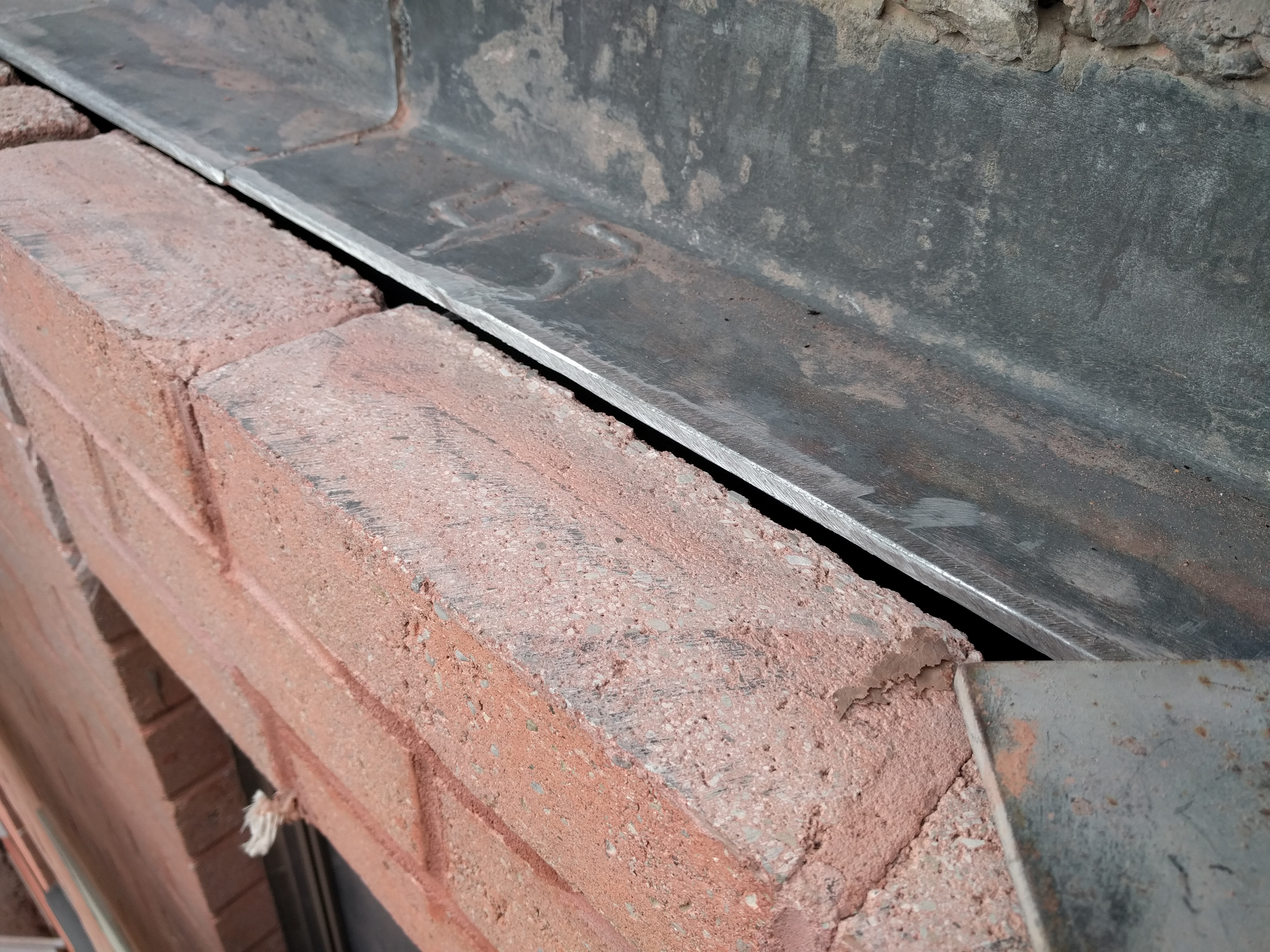
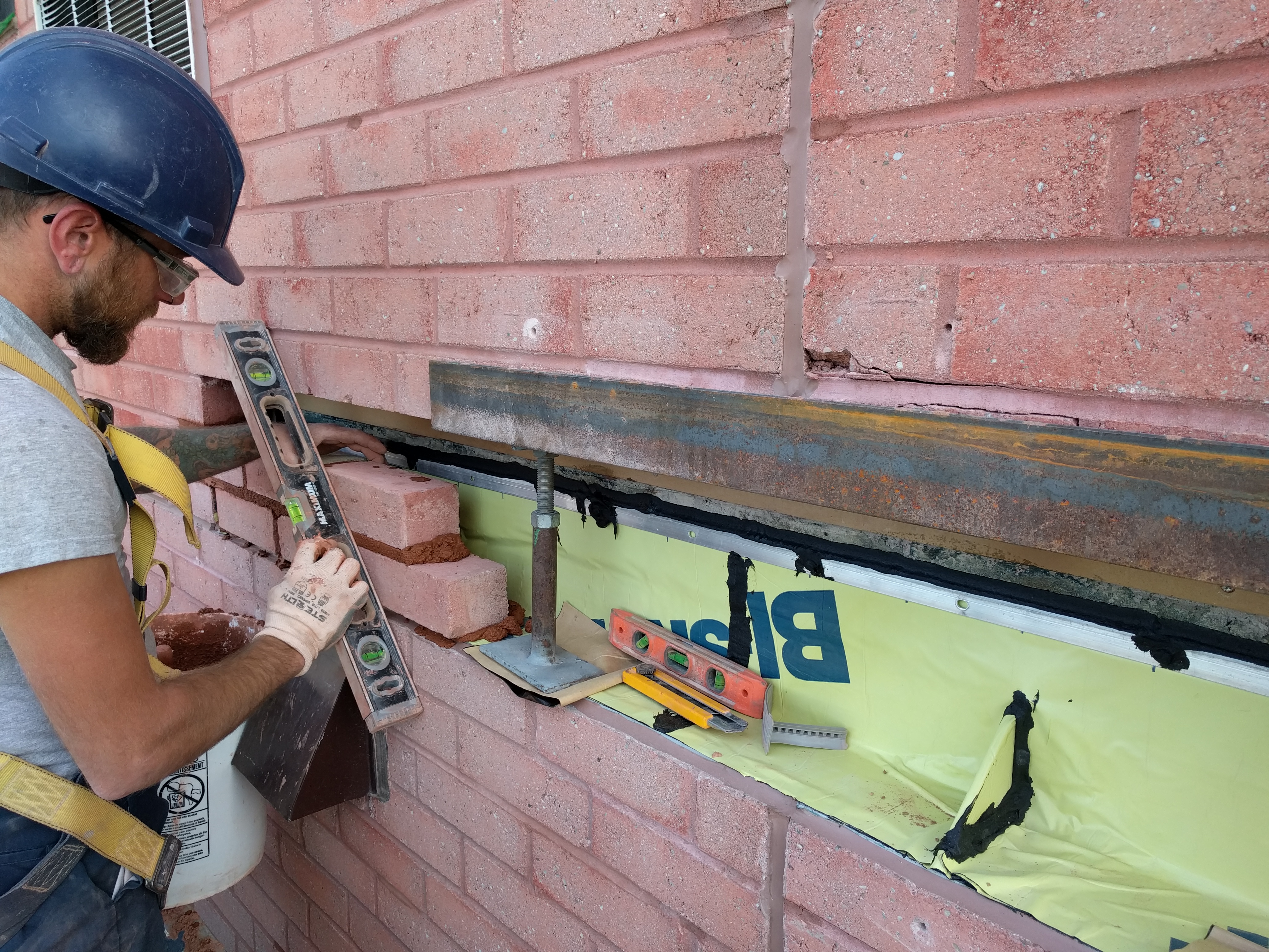
Full exposure of all shelf angles to check overhang would have been unduly costly. Instead, we performed localized openings at shelf angle toes to measure overhang (Figure 7). We observed some locations where the shelf angle was providing inadequate support, and some locations where the shelf angle was providing no support at all (Figure 8).
We carried out structural analysis of the existing shelf angle systems and confirmed that two stories of masonry could be safely supported by one shelf angle. This allowed for a significant reduction (approx. 25%) in quantity of required repairs without compromise of façade stability or safety. Additionally, this change resulted in a proportional cost savings for the owner.
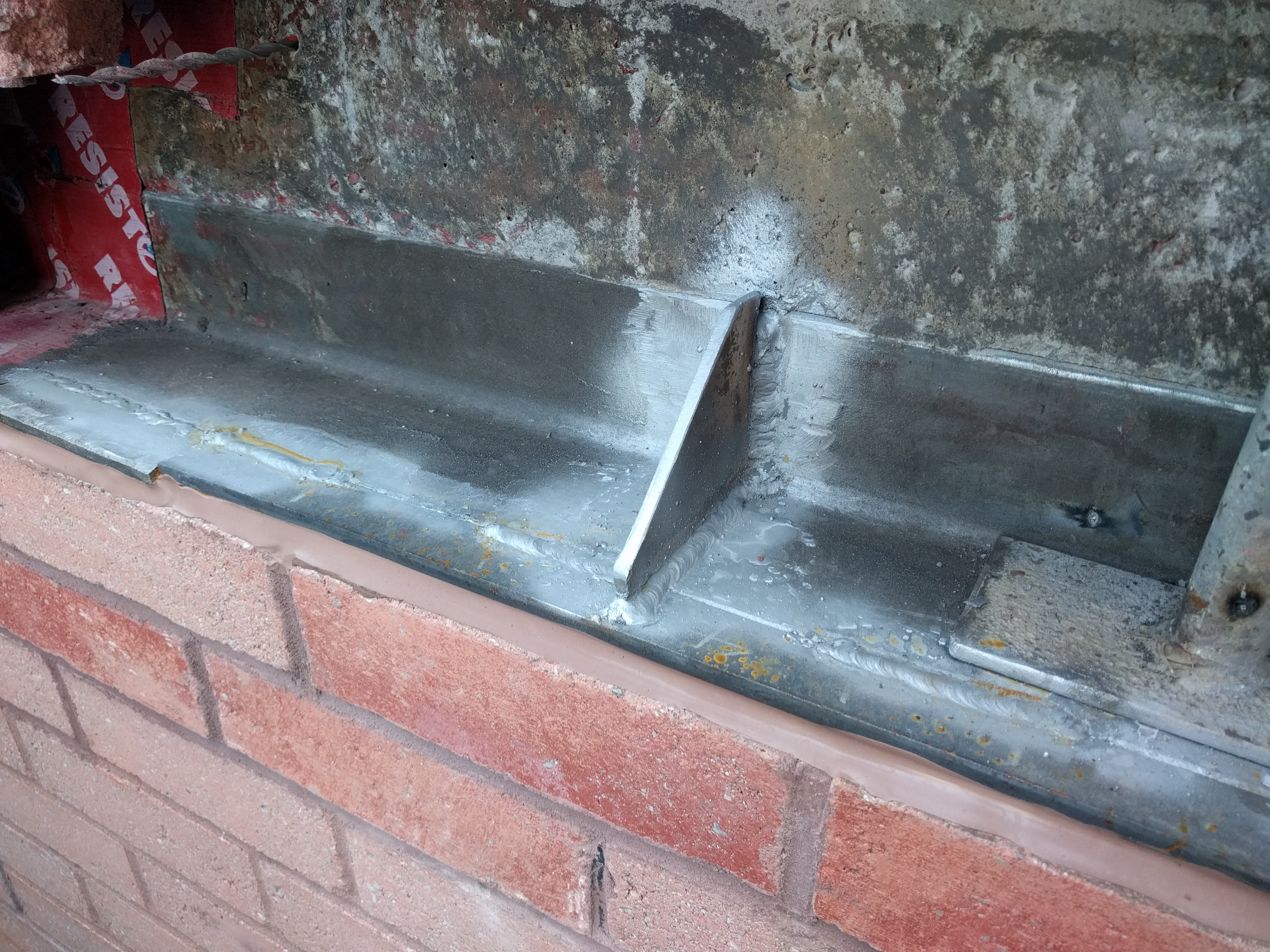
Where repairs were required, shelf angles were extended and reinforced in place with welded steel extension and stiffener plates, custom-sized based on the repair location and existing overhang (Figure 9). Stiffener plate spacing was designed to accommodate existing brick coursing. Repaired shelf angles were then waterproofed and bricks were reinstated (Figure 10).
Challenge 3: Shelf Angle Securement
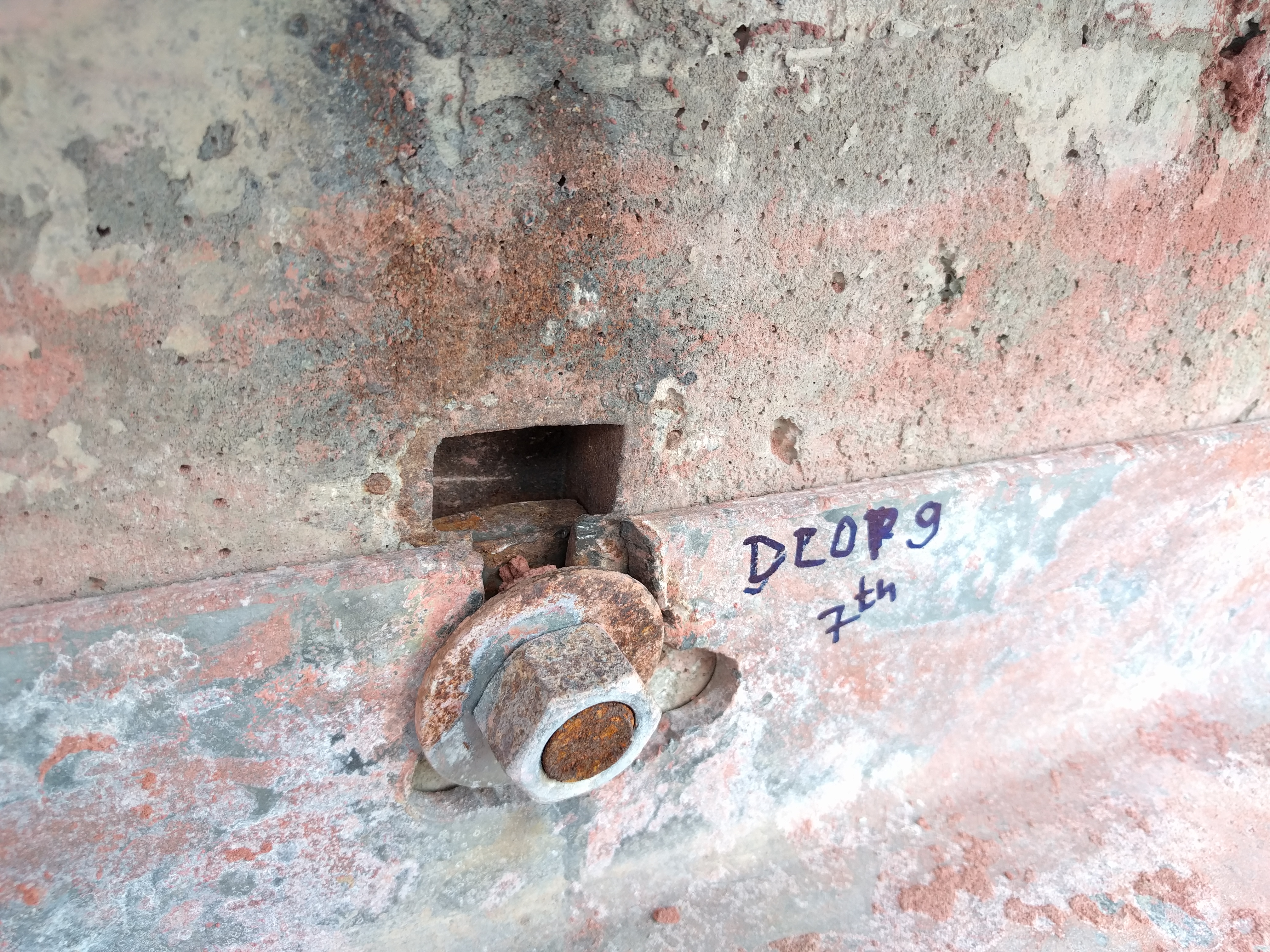
During repair implementation, we uncovered a previously unforeseen condition related to shelf angle securement. At cast-in-place concrete back-up wall areas, shelf angles were secured to the structure with T-slot bolts and washers/nuts. This method of shelf angle securement was not uncovered during the limited initial review, nor was it identified on the original construction drawings provided. As a result, we did not expect to uncover these bolted connections while conducting repairs.
Consistent with the workmanship from original building construction previously described, the shelf angles appeared to have been crudely modified on site during installation to accommodate bolt locations and masonry coursing. These modifications required repair, since they resulted in bolt slots that were oversized or too close to the edges of the shelf angle.
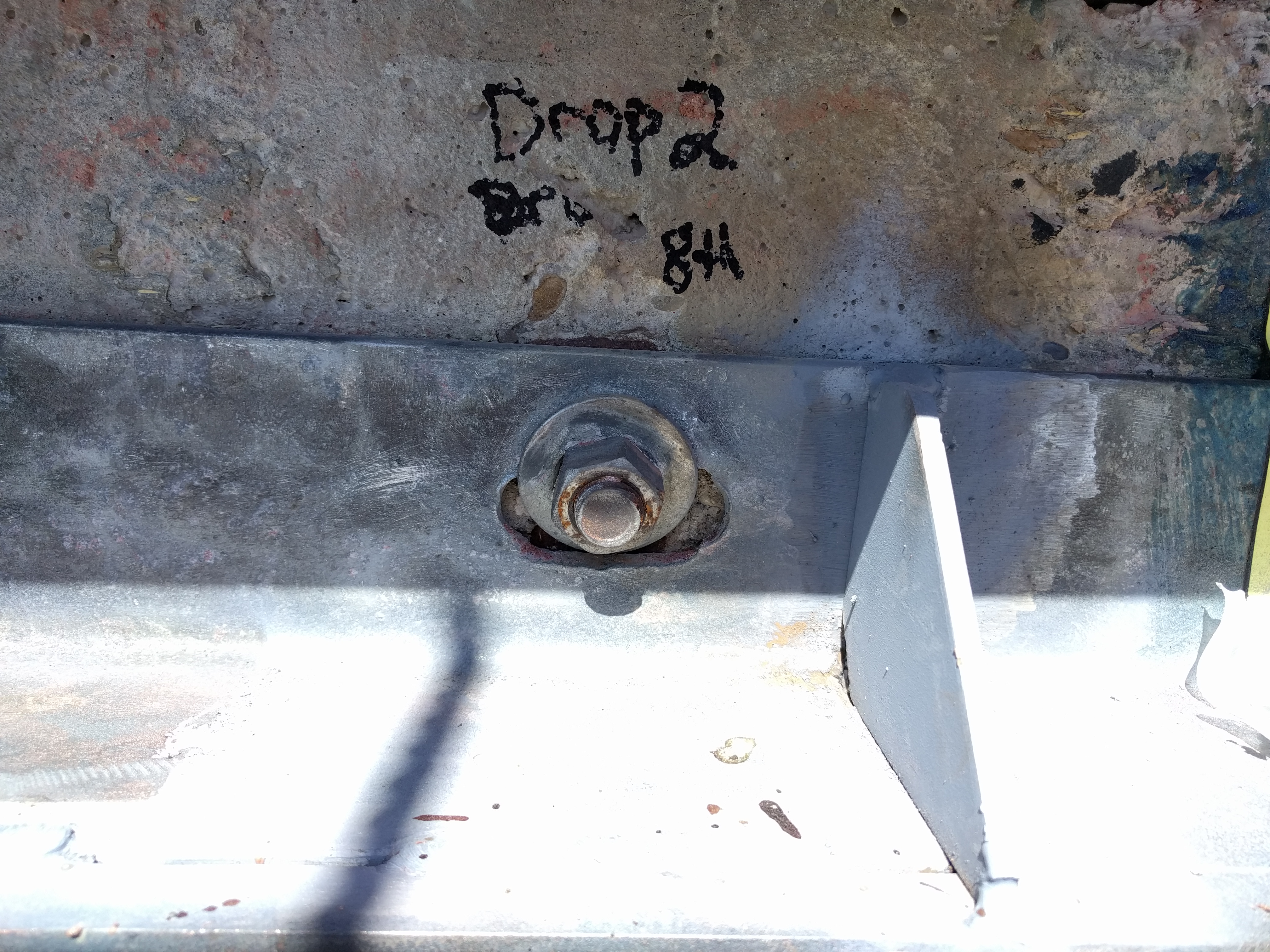
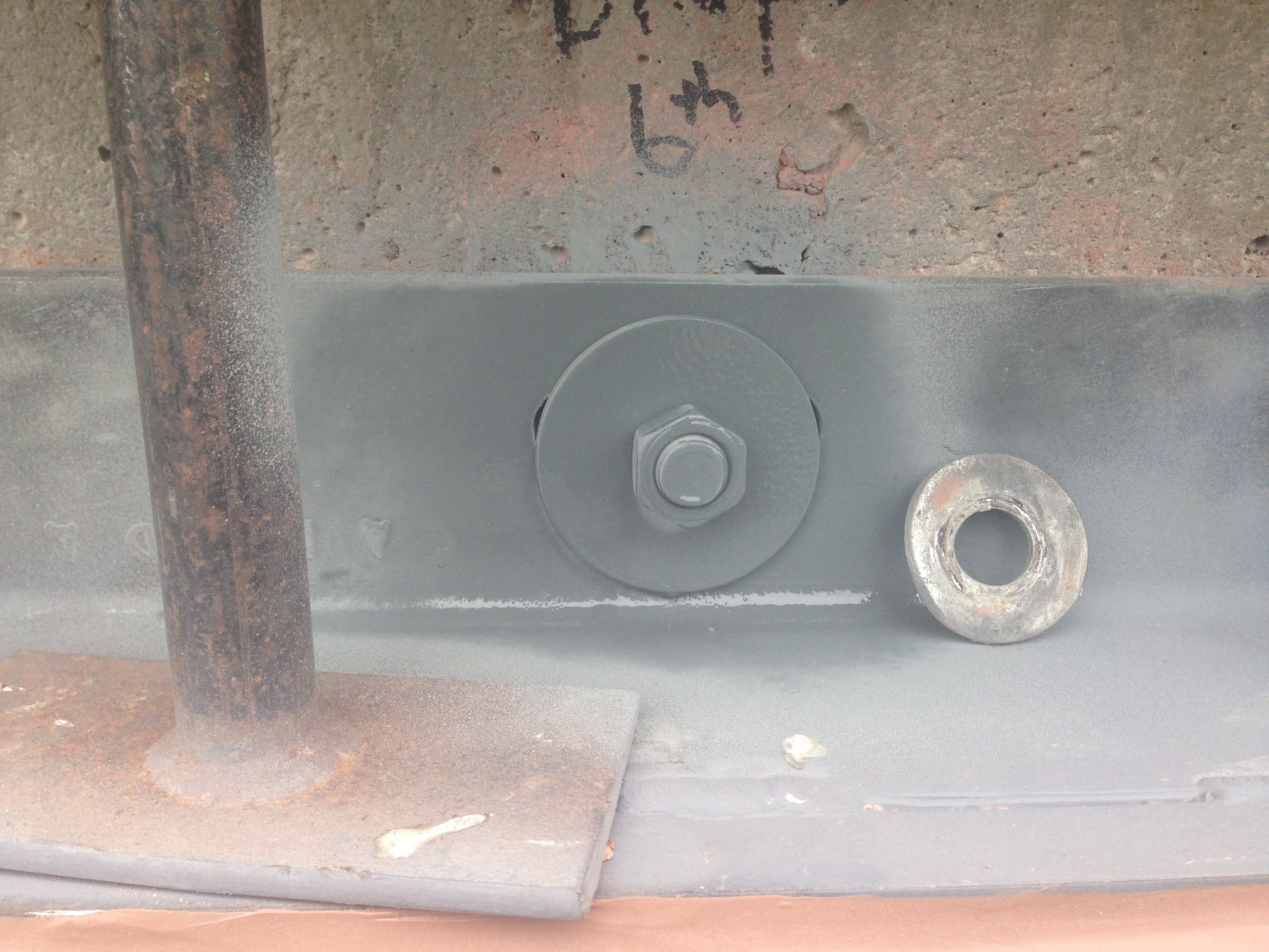
At areas with oversized bolt slots, the existing washers were not making fully contact with the shelf angle around the bolt slots (Figure 11). Fortunately, we were able to back off the existing nuts to provide a new larger washer (Figure 12).
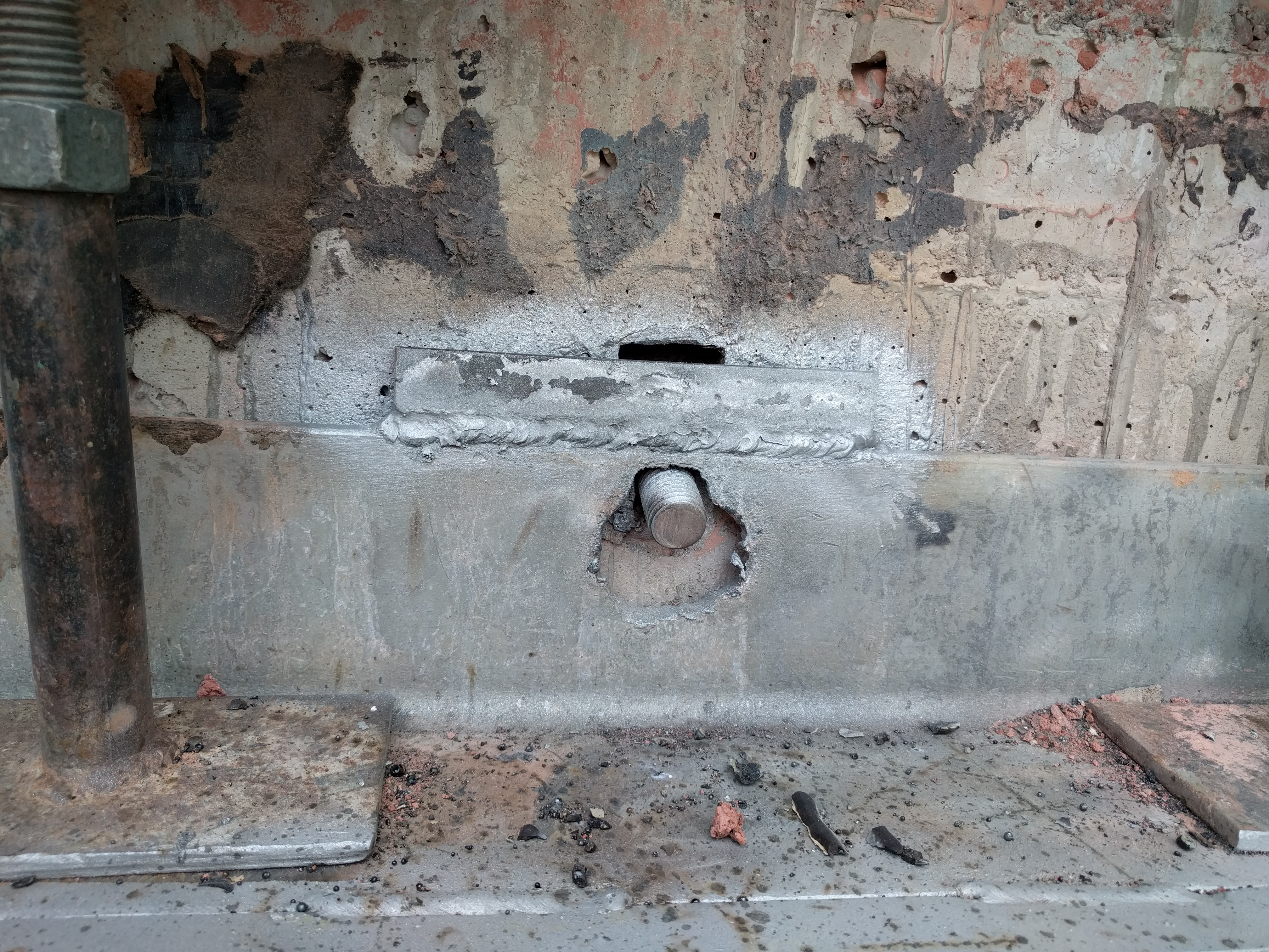
Additionally, some shelf angle modifications included full (or near full) removal of the vertical leg of the angle to accommodate bolt placement (Figure 13). These locations were repaired by providing a new welded steel plate above the vertical leg of the shelf angle, restoring adequate edge distance (Figure 14).
Shelf angle repairs also included installation of new bolt anchors where existing bolts were damaged and could not be re-used, and the addition of new shelf angles between angles with excessive unsupported distances. These localized shelf angle repairs safely eliminated the need for full shelf angle replacement—again resulting in a cost savings for the owner.
Don’t Forget About the Owner
Existing buildings are all unique, in design, construction, and performance. Owners are also unique and require a customized approach and accommodations to ensure smooth project delivery. In this case, the owner included multiple non-specialist stakeholders with a high level of interest in project cost and progress.
Perhaps this should be Challenge 4: Owner Communication and Involvement. Despite identifying creative, minimally invasive, safe solutions and opportunities for cost savings in design, unforeseen concealed conditions and uncertain repair quantities resulted in cost forecast fluctuation throughout repair implementation. Owner communication involved development of non-technical short form reporting and multiple meetings and presentations to educate the ownership group on required repairs.
Existing buildings are not always beautiful in design or architecture, but there can be an elegance in design and project implementation that will often define project success, as it did here.